

Network Device Communication :
In network when we talk about the flow of data, most of the time it means the communication between different applications. The applications generate data at layer 7 and the device / host sends data down the OSI model. As the data moves down the OSI model it is encapsulated or modified as needed.
At Layer 3, the device/ host decides:
- Whether the data needs to be sent to another application on the same device, and it would then start to move the data up the stock of layer.
- If the data needs to be sent to a different device, / host continues processing down the OSI model toward Layer 1, layer 1 is responsible for transmitting the information on to the media (which cable, fiber, or radio waves). On the receiving side, data starts at Layer 1 , then moves to Layer 2 , and so on , until it has moved completely up to layer 7 and on the receiving application.
Layer 2 Forwarding:
Each Layer 2 technology uses a different addressing mechanism for data communication.
For Example Ethernet uses MAC address, Frame-Relay uses DLCI and MPLS uses Labels.
CCNP focuses more on Ethernet and wireless tech both of them uses MAC address for Layer 2 addressing.
MAC address :-
48 bits
2 Parts
1st part is known as OUI (Organizational Unique Identifier).
OSI Model:
Layer 7 (Application) Interface for receiving and sending the data.
Layer 6 (Presentation) Formatting of data and encryption.
Layer 5 (Session) Tracking of Packet.
Layer 4 (Transport) End to End communication between devices.
Layer 3 (Network) Logical Addressing and routing of packets.
Layer 2 (Data-Link) hardware addressing.
Layer 1 (Physical) media type and connector.
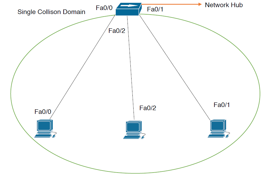
Collision Domains:
HUB:
The problem with traditional networks (using hub):
- These were devices operating on half duplex modes, creating only a single collision domain.
- Collision domain – a group of ports which share the same bandwidth.
- Only one device called send or receive data at a time, other needed to wait for the previous communication process to be over.
- If two devices start sending at the same time, collisions occur in the network and bandwidth is wasted.
- CSMA/CD process (back off timer algorithm) was used to come out of the collision.
- As more devices are added to a cable to a cable, less efficient network becomes as devices there is not any communication.
Network hubs do not have any intelligence in them to direct network traffic; the simply repeat traffic out every port. So, hub increase the collision problem because they add part density while repeating traffic, thereby increasing the size of the collision domain.
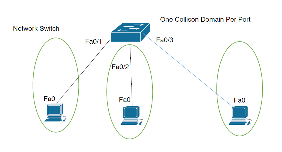
Switch:
A network switch solves this problem how?
By creating a MAC Address Table (MAT):
- Switched networks operate at full duplex mode which results in one collision domain per switch port.
- It means more than the device connected to each port can send and receive data simultaneously.
- So, instead of flooding all traffic out of every switch port, a switch uses the local mac address table to forward network traffic only to the destination port associated to the destination MAC.
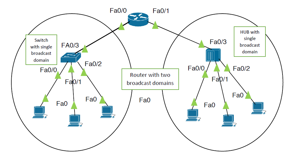
Broadcast Domain:-
It is the group of ports or devices which receive the same message/ information at the same time.
HUB:-
- A network hub has a single broadcast domain because it is essentially a dumb device with no memory whatsoever, and it is not aware of any addresses (neither IP nor MAC).
- So, what it does is simply forward the received message out of all its ports every time.
- Therefore, all devices connected in the hub network receive the same message repeatedly, which makes such networks very inefficient in terms of bandwidth utilization.
Switch :-
- Switches also have a single broadcast domain.
- However, the major difference between a hub and a switch is that a switch broadcasts only once.
- It does so when the destination MAC address is not present in the MAC address table of the switch.
- Otherwise, it will unicast.
Router :-
- Routers are the best kind of devices in this matter.
- The reason is – router have multiple broadcast domains.
- Each port of a router is a separate broadcast domain.
So, if there are 3 interfaces used of a router. For three different networks, these are three broadcast domains and by default routers never forward the traffic of one broadcast domain into another. It reduces the broadcasting problems in the networks up to a great extent.
So, it is advised that you should have a network design where there are not more than 300-500 devices in a single broadcast domain. (I is referred to as the /24 rule – means have only less than 256 device in a single broadcast domain.)
Layer 2 Forwarding Concepts:-
- Doesn’t rewrite layer 2 frames like routers does at every hop (transparent bridging).
- Take hardware (ASIC) based forwarding decisions.
- Use MAC table for forwarding decision.
How does a switch learn MAC address ?
- The switch is a layer 2 device used to connect multiple devices within a LAN segment.
- By default, the switch will broadcast and multicast on every port except the originating port.
- A switch has some intelligence and operators at layer 2 of the OSI model.
To understand this, lets take a simple example.
Lets say 3 devices are connected to a switch using 3 switch ports,
When PCO want to communicate with PC2, first it will create a packet header as following:
Source IP – its own IP (Pc1)
Destination IP the IP ( PC2)
When this packet will be forwarded to the layer i.e. L2 (data link layer ), it will create a frame (L2 PDU) and will need the source and destination MAC address.
Source MAC – its own MAC (pc0)
Destination MAC-? ( unknown)
Now, it has the source MAC address.
Run the following command in the PCO:
Arp -aAnd you will see this output: no ARP table entries found.
So, to resolve the MAC address of the destination, here comes the concept of ARP ( address resolution protocol).
Address Resolution Protocol –ARP
To find the MAC address of the destination device, the ICMP request (L3 PDU) will be generated which is known as ARP request.
This ARP request will then handover its request to the layer 2 ARPA protocol which in turn will be sent through the physical link to the next device (switch in our case).
ARP PACKET:-
Source MAC – 0000.bc73.1c8B
Target / destination MAC – 0000.0000.0000
ARPA FRAME:-
SOURCE mac – 0000. BC73 . 1C8B
Target / destination MAC – FFFF. FFFF .FFFF
So, remember that ARP is a layer 3 protocol which perform its function with the help of layer 2 ethernet encapsulation process.
Now, when this ARP frame is received by the switch, it will store the MAC address of PCO in its ,MAC address table at interface fa 0/1. Then it will see that the destination MAC address is broadcast MAC address ( FFFF. FFFF. FFFF.).SO, switch will forward this frame to all of its ports except fa 0/1 ( where the ARP request we received – it is to prevent the loop).
Now , only that device will reply who has the destination IP set in the ARP request ( 10.0.0.2) in our cast and all other device will reject the request . so, when PC2 will reply , the switch will save the MAC address of PC2 in its MAC address table at interface fa 0/3
So in this way a switch creates its MAC table by using the source MAC address of the frames. When switch will forward this reply back to OCO, PCO will have the destination MAC address i.e. the MAC address of PC2 . so , it will resume the ICMP request whin was hold earlier. This is the reason why in IPVS , first packet is lost as the ARP packet.
Verification :
# show interface status
# show MAC address – table dynamic
# show MAC address – table dynamic add fa16.3a11.8d77
# show MAC address – table dynamic interface gig 0/2
NOTE:- If a switch doesn’t see a particular MAC add to 300 sec it will be removed from the MAC address table of the switch.
What if we want to manually remove something from the mac address table? Yes this is possible with the following command:
# clear mac address – table dynamic
Static MAC table entry:
Normally switch will automatically learn MAC address and fill it’s MAC address table which is also known as CAM table by looking at source MAC address of the incoming frames and flooding the frames if it doesn’t know where to forward the frame exactly.
This process is vulnerable to layer of MAC address spoofing attacks where attacks sport a certain MAC to change entries in the MAC add table. a simple method to deal with the issue is to manually configure entries in the MAC add table.
Entry, you can either specify the interface where the MAC address is located or tell the switch to drop the traffic.
(config)# mac address – table static 0000.1111.2222 V lan1 interface fa 0/1
#show mac address-table static | include fa0/1